The History and Future of Bishop Cubes
by Forrest Bishop
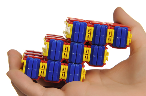
How does a thing come to be? Where do ideas come from? Where do they go? I don't have the answer to those questions. I don't think anyone does. I do know that ideas can be forgotten and lost, though. I remember now daydreaming, a long time ago, about how to make a material object that could change its shape at will- a shapeshifting machine.
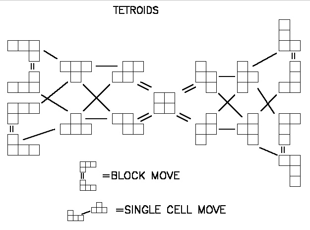
The idea that came to me was to do it with cubes that could move. This was a few months before Eric Drexler's book Nanosystems came out. When it did, I bought a copy and found within it a picture of what appeared to be... cubes that move. I decided then that my idea was not original and therefore not worth pursuing. I receive many ideas from somewhere and had many other things to do. So I forgot about the moving cubes for a couple of years.
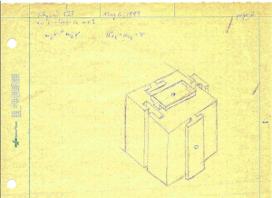
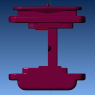
One day I was bored again in a physics class, a lecture on Special Relativity and electrodynamics. (I went on later to work on the theory of electricity; that's another story.) I had recently returned to thinking about how cubes could be made to move around. Drexler's drawing did not show a mechanism. I drew a picture of my mechanism on page 2 of my class notes of May 6th, 1994. That drawing is the genesis of what are now called Bishop Cubes®, though it appears to lack one crucial feature- it cannot move in three dimensions unless the interface on the underside is perpendicular to the one on the top.
In November, 1995 I went to a Foresight conference on nanotechnology near Palo Alto, California. I had been working on a new design for cubes-that-move, using the original idea twice on each Face. Now the cubes could move in all dimensions, though they were more complicated. Standing in the line for lunch, I met Jeffery Soreff. I started telling him about my ideas for cubes-that-move, which was the reason I went to that conference. He said “this sounds like the same thing an English fellow is promoting". There was another Inventor!
Jeff put me in touch with Tihamer "Tee" Toth-Fejel, who had also been corresponding with Joseph Michael, the other Inventor. Tee sent me some of Michael's work. I realized that his design was profoundly different from mine, though the Core Concept- cubes-that-move- was the same. I decided I had better get something into print before I lost all claims to originality (I had already forgotten about the drawing). My first paper, "The Construction and Utilization of Space Filling Polyhedra for Active Mesostructures", was written, illustrated, and published in less than three weeks. Most of this was off the top of my head, since I had been thinking about it for some time.
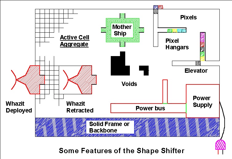
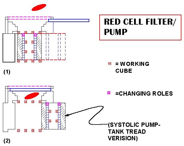
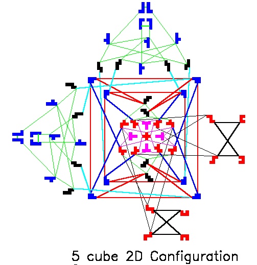
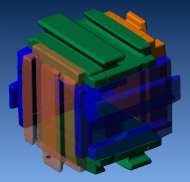
Some 1995 Shapeshifter Concepts
Some 1996 Shapeshifter Concepts
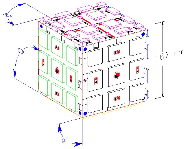
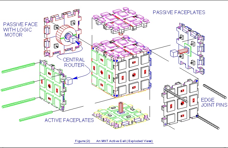
Then I went on, in early 1996, to a more detailed design, the XY Active Cell, the Overtool Universal Assembler based on that design, and Starseed/Launcher, the interstellar nanoprobe concept. In the process,
I completely forgot about the original idea.
The years rolled by and I went off to do other things. In early 2004, I heard Tee was working on a NASA project to demonstrate a Shapeshifter and a Universal Assembler, things which will be very useful in outer-space development. I suggested he consider my XY Active Cells for this project. As part of that continued proposal, we decided to do a contest of sorts, between Michael's XYZ Cells (named so by me) and Bishop's XY Cells, to see which type would be best for the demonstrator. (The "X", "XY", and "XYZ" designations are to distinguish between the fundamental types of possible movement between two Cubes, or Active Cells. Stand on a floor. If you can only move back-and-forth, or only side-to-side, that's an "X" motion. If you can move side-to-side as well as back and forth, that is "XY" motion, like an "XY" table on a machine tool. If you can also detach from the floor and lift off like a helicopter, that's "XYZ" motion.)
Rediscovery of the X Active Cell
As we worked on the NASA Phase II proposal, I sifted through my old notes, to remind myself of how these things were supposed to work. On May 5th, 2004, up turned the drawing from May 6th, 1994. In an instant, I remembered again! In a second instant, I had the solution to the original problem, of how to make these things move in three dimensions, which is to have at least one interface for each of the three directions in space. I wasn't exactly sure this would work, so I spent the next hour or so making a digital animation of the new design, which is XXOR1 agg1.AVI. I made a couple more animations shortly after that, all of which prove that these objects can be rearranged into many different shapes without ever having to take them apart- the key to a Shapeshifter.
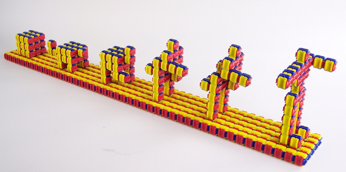
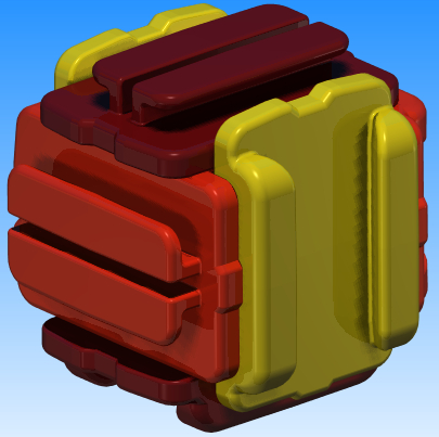
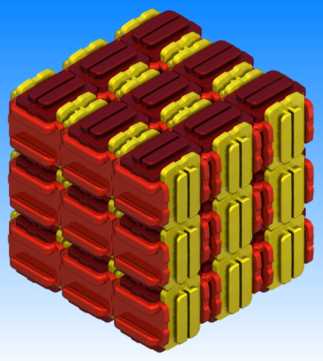
In 2006 I built the first working version of a Set of 27 Bishop Cubes. These are handmade out of hundreds of little pieces of hobby shop plastic glued together, which took a minute or two. This was the only existing example for several years. The idea was to first make a toy-model version of the shapeshifting robot because it also makes for a wonderful puzzle. I thought that would be relatively easy to do. I was quite mistaken.
It turns out that the type of Cube shown in XXOR1 agg1.AVI is not the only kind of what are now called Bishop Cubes, not by a long stretch. It turns out that there are whole families of these objects, hundreds of different kinds, with previously-unknown geometric properties: there is a little more to the elaborated cube than what Euclid told us. I made CG, three-dimensional computer models of the geometry of every possible type of X Active Cell, which also took a minute or two. This was a brute-force search, as I could not see an easy way to do this with the mathematics of permutations and group theory. After filing a patent, I wrote up a paper describing some of this- The Enumeration and Space-Tiling Motifs of Marked Polyhedra and published it on the web in August, 2007.
Although I wanted to make a mass-produced version out of injection-molded plastic, I could not see a way to do this at the time. Between all the different precision requirements of a successful design, this appeared to be beyond the capabilities of injection molding. Each Cube, at about 3/4" wide, has to be within a very few thousandths of an inch across, and also in all other critical dimensions, inside and out, otherwise they will either fall apart from each other, or jam up when attempting to slide them. The handmade version holds these tolerances pretty well, but the number of zeros in the sticker price is quite shocking.
So, in 2008, while continuing to hem and haw on a wide variety of injection-molded design ideas, I decided to try to make a version out of solid machined and anodized aluminum. With three, or maybe four, figures in the suggested dollar price, these would also have had a sticker-shock problem, but not nearly as shocking as the handmade version.
Aluminum Prototypes
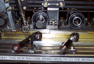
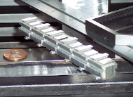
As these would be milled out of solid bar stock, I scratch-built two machines for this purpose, named "Facer" and "The New Machine". Both worked pretty good. "Facer" faced off the bar stock to bring the overall dimensions into tolerance, in preparation for all of the other milling operations that would be needed. "The New Machine" was a multi-spindle, horizontal milling machine with a continuous feed for the bar stock. The picture of it shows a brass carrier for the faced-off bar stock, and an aluminum work piece sitting in the carrier. This can only do two, or four, of the six sides of a cube, so another machine was planned to cut the bar into short pieces and mill the remaining two or four sides. I didn't get that far with it: the pictured 6" milled aluminum bar was the stopping point for two reasons. The amount of detail work that would have be needed in order to outfit and finish each Cube was quite daunting, besides, I had finally come up with an intriguing set of injection-molding concepts and designs.
Bishop Cubes Model I
After a few years of design work I discovered some more novel and astonishing geometries, including the breakthroughs that finally made the plastic, injection-molded versions possible.
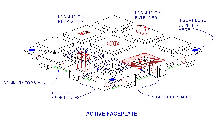
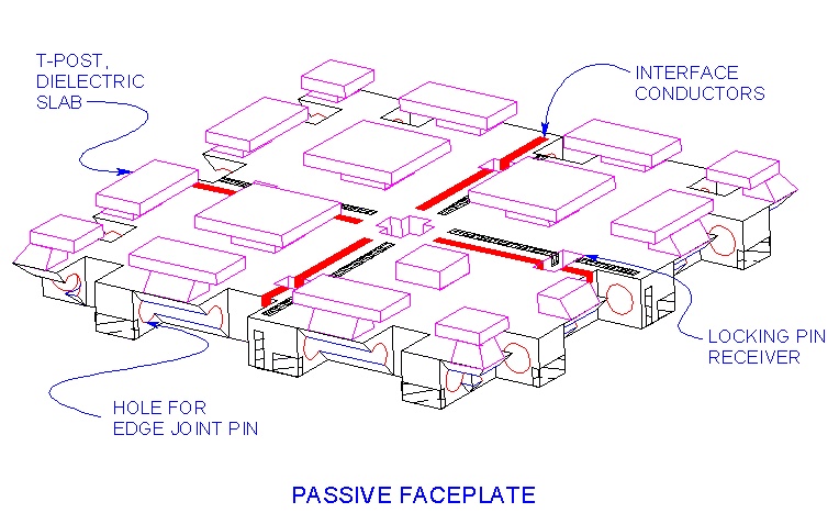
There may not be any way to make these kinds of cubical objects in a mold that isn't destroyed after its first use. Each of the six Faceplates has to have undercuts in order to form the sliding interface, and each one of them prevents the release from the mold. So the Cubes would have to be molded out of some number of pieces, with six Faceplates being the most obvious and least desirable. But that still doesn't solve the undercut problem- the Faceplate-type of injection mold would still have to use expensive and finicky side actions, hem haw.
At the same time, more parts = more problems. For a Set of 27 Cubes, each part added to a single Cube is 27 parts added to the Set. Each Cube part also has to join up with the other Cube parts to make the Cube, which means that all of the joints also have to be nearly perfect, to within a couple thousandths of an inch. That joining and assembling also has to be repeatable over thousands or millions of cycles. Now, plastic objects are glued or welded together all the time, but not usually to these tolerances, and most certainly not to all six sides of an object with these tolerances. This is one of the several items that make Bishop Cubes qualitatively different from all other artifacts. There are enough unusual features about these designs to warrant a paper in a putative Journal of Injection Molding.
Some Early "TT" Concept Designs
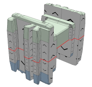
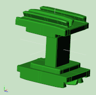
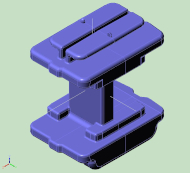
All of the prototype injection-molded Cubes, including Model I, are built out of three identical parts that come from a single mold. One of the parts is unmodified, the second one has half of its internal bridge, which connects two opposing Faceplates, removed, and the third part is cut into two pieces, so that the pieces can be assembled into a single cube. The Bridge Test was an early part of that development.
Production Designs
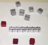
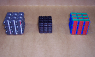
The first injection-molded, prototype Set of Bishop Cubes is the small black Set in the pictures. One problem, the Cubes of this Set are too small for larger hands, so the rest of the molded designs were built nearly the same size as the original handmade Set. Another problem, it is difficult to figure out how to put it back together after removing Cubes from the Set. This is partly because of the all-black color, but mostly because the Faceplates are all identical; the assembly orientation isn't obvious. The 2nd molded prototype Set was done in Red, Green, and Blue as a 'TS' design. The 3rd molded prototype Set is all-black, and also 'TS'. The fourth molded prototype became Model 1.
Model I Computer Graphics
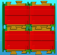
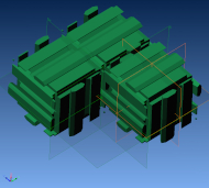
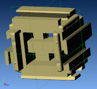
As with the rest, I modeled the Model I extensively in a CAD/CAM program before building its mold, paying particular attention to how the production machinery was going to be able to handle its parts. Another tricky aspect, not very obvious, is arranging the internal geometry so that all three identical parts can interface and weld together with each other in the three different orientations.
Injection-molded Prototypes
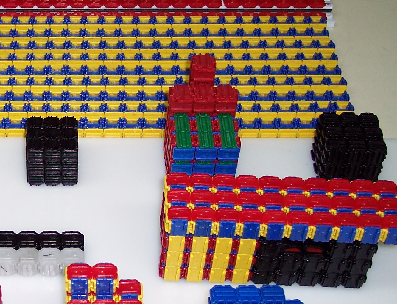
For low-volume production I built several semi-automated machines and jigs to fit the Model I parts. The "Facer" machine for the solid aluminum Cubes was put aside. A new "Loader" machine accepted the random molded pieces, sorted them out and loaded them on to rails with a pneumatic drive system. This performed several very light machining, forming, and finishing operations. "The New Machine" got added on to, subtracted from, modified, accessorized, and computer controlled. It was used to notch the Bridge, cut the Faceplates in two, perform a few light machining and cleaning operations, and to automatically assemble two of the parts, the yellow and blue strands in the all-prototypes picture. The production machinery co-developed with its product.
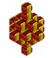
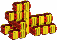
Examples of 27 Shape-shifted Bishop Cubes
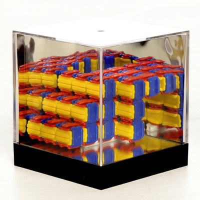
Retail and Collector's Editions of Model I Bishop Cubes®
Although they are a viable product, the Model I Bishop Cubes still requires a lot of post-molding machining and tuning to get them to work just right. They also suffer from what I dubbed the "9-to-1" problem, which is to say, it takes nine times as much force to move nine Cubes as it does to move one Cube. Starting in late 2012, I came up with some more inventions and design ideas that would both make the Cubes easier to manufacture, and would solve the 9-to-1 problem at a stroke. This would be Model II. It is still under wraps, because after that, and continuing to the present, I came up with yet another series of key breakthroughs, the ones that will make the robotic versions economically feasible. Model II remains on the shelf.
Robotic Bishop Cubes
The Bishop Cubes toy-puzzle was originally a diversion from the principle goal, which is the robotic Shapeshifter. It turns out that it has another role to play in the development of the real Shapeshifter, as a "hands on" simulator.
For a Shapeshifter, the 9-to-1 issue isn't a problem, it is a strength. The more Cubes that can act in concert, the more force they can develop, right up to the force that would disintegrate them.
A key measure of the performance of this kind of cellular machine is what I call the "Lift Number": how many identical Cells can one such Cell lift in the one-gravity of Earth? A strong man can lift 1, 2, or possibly 3 others of the same weight. Weighing 188 kg (414 lb), world champion Hafpor Julius Bjornsson can lift 501 kg (1105 lb), which is 2.66 times his weight. It may be that other men can lift somewhat more than this as a multiplier of their weight, so say a maximum Lift Number of 3 for men. The current world record for a cellular robot is 5- which seems impressive compared to men, but is not so impressive when we consider the scale factors, the Square-cube Law in particular. The Lift Number for an ant is 20, or 50, or maybe even 5000 similar ants (there are different numbers on search).
It turns out that a Lift Number of 5 is not that useful for a cellular robot. The resulting machine cannot lift itself off the ground without using at least one of every six of its Cells to do that. It can't develop very much force to push or pull. If each Cell weighs 100 grams, then each Cell can push 500 grams around. But if the Lift Number was 50, each such Cell could push 5 kg around, and a single Cell could lift up 50. This is more like what we find in useful toys and tools. It marks the difference between a laboratory curiosity and a real-life machine.
The component testing, together with the engineering calculations, suggest that the first Robotic Bishop Cubes will have a Lift Number that surpasses the current world record by about an order of magnitude.
to be continued...
I've been working on Bishop Cubes® since the early 1990's. I built a manually-operated, physical model in the mid-2000's and a more refined version later sold as Bishop Cubes®. Robotic versions are in development.
www.forrestbishop.mysite.com www.iase.cc © Forrest Bishop
